| Setting |
Possible Values |
Description |
| iSimConnect |
AUTO
P3DV3x
P3DV3
P3DV22
P3DV21
P3DV2
P3DV14
P3DV13
SP2
RTM
|
For certain functions like
traffic population and other built in functions that rely on the
presence of SimConnect, this value defines which version of
SimConnect to expect on the computer. If no match is found, the
highest available version of iSimConnct is used.
It is strongly
recommended that you use AUTO unless you have a specific
reason to change it.
Leaving the setting out of the INI file altogether
results in AUTO being automatically selected for you. |
| CheckForUpdates |
YES
NO |
This setting is for future
use. There is a facility inside the G1000 that can check
whether a new version of the software is available. But
this facility is temporarily out of service used until it can be further
enhanced. At this time, this option should be set to NO. |
| GpsRedrawRate |
1 - 10
Default is 4 |
The real G1000 does not
update the moving GPS map as quickly as flight simulator does.
This setting defines the number of seconds in between moving map
updates. For performance reasons, this setting should
not be changed unless a problem is occurring. |
|
NrstRange |
10-100 |
Specifies the number of
nautical miles to be used as a radius when create a list of items
in the G1000 "nearest" pages, such as nearest airports, nearest
VOR's, nearest NDB's, etc. |
|
MAP_ORIENTATION |
NORTH_UP
TRACK_UP
DTK_UP
HDG_UP |
Specifies the orientation of
the various GPS maps in the various G1000 screens. |
|
AUTO_ZOOM |
YES
NO |
Specifies whether the moving
map automatically zooms closer into a waypoint as the aircraft is
about to pass the waypoint. |
|
SHOW_TRACK_VECTOR |
YES
NO |
Specifies whether a cyan
arrow emits from the small airplane on the moving map, indicating
where the aircraft will be in 10 seconds based on current ground
speed. |
|
SHOW_WIND_VECTOR |
YES
NO |
Specifies whether the MFD
should display a small box in the upper right corner indicating
the direction and strength (ini knots) of the wind. The
heading and direction are computed from GPS information. |
|
SHOW_NAV_RANGE_RING |
YES
NO |
Specifies whether a
compass-rose type circle is drawn around the aircraft on the
moving map, showing tickmarks for various headings around the
aircraft. |
|
SHOW_TOPO_DATA |
YES
NO |
For future use. |
|
SHOW_TOPO_SCALE |
YES
NO |
Specifies whether a small
color legend is displayed on the MFD moving map showing the colors
of various elevations of terrain. |
|
SHOW_TOPO_MAP |
YES
NO |
Specifies whether colored
topography is displayed on the moving map. The colors are
standard, and are based on the ground elevation of the area being
depicted. |
|
SHOW_TERRAIN_DATA |
YES
NO |
For Future Use. |
|
SHOW_OBSTACLE_DATA |
YES
NO |
For Future Use. |
|
SHOW_FUEL_RANGE_RING |
YES
NO |
Specifies whether two
concentric green circles are drawn on the MFD moving map to denote
the range of the aircraft when the fuel level reaches the
authorized reserve quantity, and when it runs completely out of
fuel. The calculation is based on current fuel consuption levels. |
|
KNOB_ACCEL_THRESHOLD |
0 - 1000
Default is
220 |
Defines how many
milliseconds in between HDG or CRS knob events constitutes a
"rapid twist". If the HDG or CRS knob events arrive faster
(lower number of milliseconds than specified here), then they are
acted upon in "rapid" mode, causing the HDG or CRS value to change
in 10-degree increments instead of 1-degree increments.
A value of 0 means no knob acceleration will be used. |
|
SHOW_DCSFRA |
YES
NO |
After the 9/11 attacks, a
number of special airspaces were defined around the Washington DC
area. At the present time, this special airspace is a
"Special Flight Rules Area" or SFRA. This setting specifies
whether the Washington DC SFRA is to be depicted on the GPS moving
map with yellow lines and arcs. |
|
SHOW_INTERCEPTOR |
YES
NO |
When used in combination
with the SHOW_EASTER_EGGS option, and if the easter egg option in
the G1000 for "AI Traffic" is turned on, this setting specifies
that a Civil Air Patrol aircraft should intercept your aircraft if
you enter the Washington DC SFRA while squawking a transpoder code
of 1200. |
|
SHOW_EASTER_EGGS |
YES
NO |
Specifies whether a set of
secret options called "easter eggs" become available when pressing
the blank softkey between ENGINE and MAP on the MFD.
For more information on the easter egg functions, refer to
G1000 Easter Egg Functions. |
|
SHOW_METRIC |
YES
NO |
Specifies whether the
altimeter displays metric values for altitude and the altimeter
setting. An additional box showing meters appears next to
the altimeter in addition to feet, and the Kohlsman window on the
altimeter switches to hPa (millibars / hectopascals) |
|
SHOW_HPA |
YES
NO |
Specifies whether the
Kohlsman window showing the altimeter setting should display hPa
instead of inHG (hectopascals/millibars instead of inches of
Mercury). This setting
overrides the SHOW_METRIC
setting. |
|
SHOW_METERS |
YES
NO |
Specifies whether the
altimeter should display an additional box showing meters next to
the center of the altimeter tape, in addition to the tape showing
feet.
This setting
overrides the SHOW_METRIC
setting. |
|
SHOW_ALL_INSTANCES |
YES
NO |
If the G1000
appears in the panel.cfg in a popup window as well as in the 2D
cockpit and/or the 3D Cockpit, the G1000 will stop displaying
anything on the panel mounted instances of the G1000 when the
popup version (zoomed version) is visible. This is done to
preserve frame rates, otherwise many computers would struggle with
sluggish performance during the time that both the panel mounted
unit and the one and the popup are both visible simultaneously.
To inihbit this performance-saving feature, you can set this
option to YES, but it is strongly discouraged due to the potential
adverse impact on simulator performance. (This feature was
introduced in the Spring of 2017). |
|
ITUNES_AS_XM |
YES
NO |
For future use. This
is a facility inside the G1000 that will utilize any installed
copy of iTunes on the computer to play music controlled by the
G1000 XM Radio screens. This option is not fully tested at
this time, and may cause flight simualtor to crash. |
|
MFD_DATABAR_FIELDS |
Comma Delimited List
of 4 values:
GS
DIS
ETE
ESA
BRG
DTK
END
ETA
FOB
FOD
MSA
TAS
TKE
TRK
VSR
XTK |
The G1000 has the option to
change what values are displayed at the top of MFD in the magenta
GPS section. This section is called the MFD Databar, and can
be set by the G1000 AUX screens. Whatever settings are
selected by the pilot are saved here. Four items are
always saved, separated by commas, with no spaces. |
|
NAVDATA |
MICROSOFT
REALNAV |
This setting controls which
navigation database is used by the avionics. If you
are using Prepar3D, the MICROSOFT setting will still use the data
internal to the sim. |
|
LOCCOURSE |
Blank by Default
or
DB |
Some international
certification authorities in Europe require that the final
approach course be displayed exactly as specified by the
navigation database, even if this is not the magnetic course you
fly to get to the runway in the flight sim world. The
LOCCOURSE=DB option ensures the localizer course on the HSI is set
to the value published in the database instead of the value coming
from the localizer in the flight sim scenery. The down-side
of this option is that the green needle on the HSI may not point
straight ahead when you are exactly on course, it will point
slightly left or right by a degree or two. This happens due
to differences in the flight simulator map projection and magnetic
variations. This option should NOT be used unless you are
trying to use our professional edition in a real world simulator,
and you are experiencing certification difficulties with your
particular aviation authority. |
|
DISABLE_AUTOPILOT |
YES
NO |
Some international
certification authorities in Europe require that if the autopilot
does not operate EXACTLY like the one in real aircraft in their
country, that the autopilot must be disabled in the simulator.
Since FSX, ESP, and Prepar3D will always have some minor
differences between the real world and the simulated world, this
option is sometimes necessary in order to pass certification.
This option should NOT be used unless you are trying to use our
professional edition in a real world simulator, and you are
experiencing certification difficulties with your particular
aviation authority. |
|
TRANSPONDER_VFR_CODE |
Blank by Default
or
any valid 4-digit
4096 transpoder code. |
In the United States,
"squawk VFR" usually means set your transponder code to 1200. But
there are some special cases where another code, for example 1226, is used
as the VFR squawk code. Furthermore, in some other outside the United States,
the VFR code is not 1200. For
example, 7000 is used as the VFR code in some locations.
In the G1000, one of the softkeys on the PFD is titled VFR, and
will switch the transponder code to the appropriate VFR code.
If you are in a country that uses something other than 1200, enter
that code on this line to make the G1000 tune that code in response to pressing
the VFR softkey on the PFD. Make sure you use a VALID 4096-transponder code.
An invalid code on this line could cause flight sim to crash. |
|
PFD_WIND_OPTION |
0
1
2
3 |
This option specifies the
default mode of the wind vector box shown on the PFD on the left
side of the HSI. The wind vector box can always be
controlled from the PFD softkeys, but this option designates what
mode comes up as the default mode when the simulator first
launches.
Option 0 means no wind vector is displayed on the
PFD
Option 1 means display two fixed arrows for the
head/tail wind, and crosswind, with numbers next to each arrow to
denote the speed of that component.
Option 2 means display
a single arrow showing the direction and speed of the wind
relative to the longitudinal axis of the aircraft.
Option 3
means display a single arrow showing the direction of the wind,
and two numbers, one for head/tail wind component, and one for the
crosswind component.
|
|
BLOCK_REPEAT_EVENTS |
YES
NO |
In some hardware, there can
be a problem if the hardware fires more than one event of the same
type in the same flight simulator tick cycle. If this option
is turned on, the G1000 will ignore all identical events except
the first one within the same tick cycle in flight sim.. This
option should not be used unless you are experiencing this
specific problem. |
IgnoreFontScaling
|
YES
NO |
Starting in
mid-2016, our gauges were modified to automatically compensate for
users who adjusted their Windows settings to use font-sizes
greater than 100%. This ensures that the fonts do not
appear excessively large in the avionics. However, some
computers whose Windows settings have the font-size set higher
than 100% will display exessively SMALL fonts in the avionics
because the automatic compensation erroneously scales the font
down. Add this optional setting to the G1000.INI and
set it = YES to tell our software to bypass the automatic font
size adjustment. |
|
FSUIPC |
YES
NO |
Can optionally
tell the G1000 software to bypass any initialization and/or
interaction with FSUIPC. (Note this does not fully remove
FSUIPC from a simulator's operation because FSUIPC operates
independently of any individual gauge. This function simply
tells the G1000 software to not attempt any interaction with
FSUIPC, even if some events are coded to "listen" to FSUIPC.
The G1000 software does not require or utilize FSUIPC except for
those cases where a customer wants to trigger G1000 events using
FSUIPC offsets. However, some versions of FSUIPC can cause
problems with the G1000 because of FSUIPC's past reliance on some
buggy Flight Sim functions. Using FSUIPC for this purpose is
not ideal since SimConnect offers a much more robust capability |
|
GPS_QUERY_TIMEOUT_SECONDS |
5 |
Defines how long
the G1000 will wait for a response from the internal Flight Sim
database when querying for waypoints. This has no
effect on RealNav. This is only for the G1000's interactions
with the built-in GPS. In other words, even if RealNav
is being used, the internal Flight Sim GPS database is still used
by the G1000 for certain queries. But because it
can sometimes operatly slowly on some systems, the timeout value
might need to be adjusted. |
|
FAST_BOOT |
YES
NO |
Adjusts the G1000
bootup simulation to be faster than real-world. This
controls the rate at which the initial message "INITIALIZING
SYSTEM" appears and lingers, and the time it takes for each of the
simulated LRU's come online. Note that if
AnimateStartup is set to "NO" in any individual aircraft's section
in the INI file, then this FAST_BOOT option will have no effect
since AnimateStartup=NO will take precedence and inhibit any
bootup animation. |
|
TIME_FORMAT |
UTC
LOCAL12
LOCAL24 |
Tells the G1000 what format
to use for displaying local time at the bottom of the PFD.
UTC means time display shows GMT Universal Time in 24-hour format.
LOCAL12 means the time display shows local time in 12-hour format.
LOCAL24 means the time display shows local time in 24-hour format.
|
|
COM_SPACING_833 |
YES
NO |
When set to YES, this
option tells the G1000 to use 8.33 kHz spacing between COM frequencies.
If this setting is omitted, or set to NO, then traditional 25 kHz spacing will be used.
At the time of this writing, FSX and Prepar3D do not
support 8.33 kHz COM channel spacing. This setting allows 8.33 kHz spacing to appear
on the G1000 screen, but the simulator environment considers many of these frequencies to be invalid.
Therefore, the flight simulator envionment will still receive radio transmissions on the
closest matching frequency in the 25 kHz spacing range even when the 8.33 kHz option
is turned on. |
| Setting |
Possible Values |
Description |
| Style |
0-999
Default 3 |
Specifies the style
of G1000 that should be displayed.
1 = Beechcraft
(Generic)
2 = Cessna 172S
3 = Cessna 182T
4 = Cessna
Turbo 182T
5 = Columbia (Professional Sims Only)
6 = Diamond
DA-40
7 = Diamond DA-42
8 = Mooney
9 = Cirrus SR-22 Turbo
10 = Cessna Citation Mustang
11 =
Generic Twin Turbine (standard MFD with radios)
12 = Beechcraft
Baron
13 = Piper Meridian
14 = Beechcraft Bonanza
15 =
Tecnam P2006T Twin (STEC-55 Autopilot Only)
16 = Piper Mirage
17 = Piper Matrix
18
= Cessna Caravan
19 = Cirrus SR-22 (non-Turbo)
20 = Cirrus
SR-20
21 = Generic Twin Turbine B (MFD is GDU-1500)
22 =
Piper Archer
23 = Piper Seminole
24 = Generic Twin Turboprop (similar to a King Air)
25 = Piper Seneca
26 = Cessna 206 (Normally Aspirated)
27 =
Cessna T206 (Turbocharged)
28 = DA42 with Lycoming L360 Engine
29 = Tecnam P2010
30 = Turbo Commander TC690
|
|
NXI |
YES
NO |
Setting this value
to YES causes the G1000 interface to display as the newer G1000 NXI layout. |
|
Accusim |
YES
NO |
This settings tells
the G1000 to obtain certain engine values from the A2A Accusim
system instead of obtaining information directly from Flight Sim. |
|
EnableRFD |
YES
NO |
Normally, only certain aircraft styles support a double-PFD (what we call the RFD for "Right Flight Display").
But if you plan to use an RFD in configuration that does not normally use one, you must set this value
to YES int the particular aircraft section you are working with. This setting tells the internal G1000 software
to force the existence of an RFD even if the selected style does not usually support one.
|
|
Checklist File |
|
Filename of a
pseudo-XML style text file that defines the aircraft checklist
items to be displayed in the G1000 screens. The
filename can be fully qualified with a path, or if no path is
included, the file is assumed to exist in the InstallDir (usually
Program Files (x86) \ Mindstar \ Flight
Simulator Addons) |
|
ShowCirrusFuel |
YES
NO |
This setting only
affects the Cirrus styles. It defines whether the MFD
displays the fuel screen during system power-up. |
|
ShowBezel |
YES
NO |
Optional setting
that specifies whether the bezel and associated knobs and buttons
are displayed as part of the G1000 display units. This
value can be set to NO so the CRT portion of the PFD, MFD or RFD
completely fill the gauge. Useful when a hardware enclosure
is used around a montor to provide physical knobs and buttons to
manipulate the G1000. |
|
dig_crs_hdg_tmout |
YES
NO |
In most aircraft, the
digital readout windows of the selected course and selected heading
around the HSI will stay displayed at all times.
But in some aircraft, these windows only display for a short period
of time after the knobs are turned, and then disappear. This
setting defines whether these windows will timeout and disappear. |
|
GradientHorizon |
YES
NO |
Most G1000 PFD units
display the blue sky and the brown ground in colors that become
darker near the top and bottom edges of the screen, and are
lighter in the area nearer to the horizon line. This
is called a Gradient Horizon. But the Gradient Horizon can
be a drain on performance on some systems, causing reduced frame
rates. By default, this setting is turned off. But if
you have a system (i.e. video card) capable of supporting this
feature and the framerate impact is not an issue for you, this
setting can be turned to YES so the GradientHorizon will display
on the PFD and RFD. |
|
AirspeedRangeLowCaution |
0-999
Default 45 |
The location on the
airspeed tape where the yellow colorbar begins. Airspeeds
below this value will have a red colorbar. The yellow
colorbar ends at the airspeed specifed by AirspeedRangeFlaps. |
|
AirspeedRangeFlaps |
0-999
Default 55 |
The location on the
airspeed tape where the white colorbar begins. The white
colorbar ends at the airspeed specified by AirspeedRangeNormal. |
|
AirspeedRangeNormal |
0-999
Default 90 |
The location on the airspeed tape where
the green colorbar begins. The green colorbar ends at the
airspeed specified by AirspeedRangeHighCaution. |
|
AirspeedRangeHighCaution |
0-999
Default 140 |
The location on the airspeed tape where
the yellow high-speed colorbar begins. The high-speed yellow
colorbar ends at the airspeed specified by AirspeedRangeOverspeed. |
|
AirspeedRangeOverspeed |
0-999
Default 210 |
The location on the
airspeed tape where the red & white barberpole colorbar begins. |
|
AirspeedBugVr |
0-999
Default 55 |
The location on the
airspeed tape where the airspeed bug labeled "R" points.
Indicates show rotation speed.
Can be adjusted by the pilot in the PFD's
TMR/REF window. |
|
AirspeedBugVx |
0-999
Default 64 |
The location on the
airspeed tape where the airspeed bug labeled "X" points.
Indicates Vx best angle of climb airspeed.
Can be adjusted by the pilot in the PFD's
TMR/REF window. |
|
AirspeedBugVy |
0-999
Default 84 |
The location on the
airspeed tape where the airspeed bug labeled "Y" points.
Indicates Vy best rate of climb airspeed.
Can be adjusted by the pilot in the PFD's
TMR/REF window. |
|
AirspeedBugVg |
0-999
Default 75 |
The location on the
airspeed tape where the airspeed bug labeled "G" points.
Indicates Vg best glide speed.
Can be adjusted by the pilot in the PFD's
TMR/REF window. |
|
AirspeedBugVyse |
|
For multi-engine
aircraft only. The location on the airspeed tape where
the blue line is displayed, identifying the best rate of climb on
a single engine. |
|
AirspeedBugVmca |
|
For multi-engine
aircraft only. The location on the airspeed tape where the
Vmca red line is displayed, identifying the minimum controllable
airspeed on a single engine. |
|
AirspeedBugV1 |
0-999
Default 91 |
For jets only.
The location on the airspeed tape where the airspeed bug labeled
"1" points. Indicates V1 engine failure recognition speed.
Can be adjusted by the pilot in the PFD's
TMR/REF window. |
|
AirspeedBugV2 |
0-999
Default 97 |
For jets only.
The location on the airspeed tape where the airspeed bug labeled
"2" points. Indicates V2, the speed at which the aircraft
can become airborne safely with one engine inop.
Can be adjusted by the pilot in the PFD's
TMR/REF window. |
|
AirspeedBugVenr |
0-999
Default 118 |
For jets only.
The location on the airspeed tape where the airspeed bug labeled
"E" points. Indicates Venr, the enroute climb speed.
Can be adjusted by the pilot in the PFD's
TMR/REF window. |
|
AirspeedBugVapr |
0-999
Default 101 |
For jets only.
The location on the airspeed tape where the airspeed bug
labeled "A" points. Indicates Vapr approach speed.
Can be adjusted by the pilot in the PFD's
TMR/REF window. |
|
AirspeedBugVref |
0-999
Default 94 |
For jets only.
The location on the airspeed tape where the airspeed bug
labeled "?" points. Indicates landing reference speed or
threshold crossing speed.
Can be adjusted by the pilot in the PFD's
TMR/REF window. |
|
AirspeedBugVrVisible |
YES
NO |
Specifies whether
the Vr bug should be visible. Can be adjusted by the pilot
in the PFD's TMR/REF window. |
|
AirspeedBugVxVisible |
YES
NO |
Specifies whether the Vr bug should be
visible. Can be adjusted by the pilot in the PFD's TMR/REF
window. |
|
AirspeedBugVyVisible |
YES
NO |
Specifies whether the Vr bug should be
visible. Can be adjusted by the pilot in the PFD's TMR/REF
window. |
|
AirspeedBugVgVisible |
YES
NO |
Specifies whether the Vr bug should be
visible. Can be adjusted by the pilot in the PFD's TMR/REF
window. |
|
AirspeedBugV1Visible |
YES
NO |
Specifies whether the Vr bug should be
visible. Can be adjusted by the pilot in the PFD's TMR/REF
window. |
|
AirspeedBugV2Visible |
YES
NO |
Specifies whether the Vr bug should be
visible. Can be adjusted by the pilot in the PFD's TMR/REF
window. |
|
AirspeedBugVenrVisible |
YES
NO |
Specifies whether the Vr bug should be
visible. Can be adjusted by the pilot in the PFD's TMR/REF
window. |
|
AirspeedBugVaprVisible |
YES
NO |
Specifies whether the Vr bug should be
visible. Can be adjusted by the pilot in the PFD's TMR/REF
window. |
|
AirspeedBugVrefVisible |
YES
NO |
Specifies whether the Vr bug should be
visible. Can be adjusted by the pilot in the PFD's TMR/REF
window. |
|
AltimeterBug |
0-90000 |
Value, in thousands
and hundreds, to display for the altitude bug. |
|
HobbsCounter |
0-99999 |
Saved by the G1000
upon exiting each flight. Maintains an ongoing counter of
flight time hours. |
|
TachCounter |
0-99999 |
Saved by the G1000
when exiting each flight. Maintains an ongoing counter of
flight time hours. |
|
AnimateStartup |
YES
NO |
Specifies whether
the G1000 should display the power-up sequence when the master
switch is turned. The power-up sequence includes AHRS
alignments and other tests that appear on the PFD in the first
seconds after the master switch is turened on. |
|
AFCS |
YES
NO |
Specifies whether the G1000 should
display the GFC-700 Automatic Flight Control System (AFCS)
items on the PFD display (For example the flight director, etc).
Depending on the type of aircraft, this may also mean the AFCS
control buttons are displayed on the bezels of the G1000 units.
But keep in mind that some aircraft configurations do not use
autopilot controls on the bezels (i.e. the Cirrus or the Mustang),
but rather, require the use of an exteral autopilot controller
(see the autopilot controllers in this
link).
So its sometimes easier (although not 100% accurate) to think of
AFCS being the "opposite" of KAP140. If you aren't
using a KAP140 autopilot in your panel, then you're using AFCS as
the built-in autopilot in the G1000).
Setting AFCS to YES also
sets the aircraft to be capable of flying LPV (WAAS, for example) approaches
supported by an SBAS system. Similarly, if you set AFCS=NO (for example if you are
using the KAP-140 autoopilot) you do not have LPV capability by default. (See
additional options in the next sections for more control over LPV /SBAS Capability)
When setting AFCS
to YES, you must ensure that no other autopilots are loaded in the
cockpit. A secondary autopilot in the same cockpit with a
G1000 running in AFCS autopilot mode will cause problems with
flight operations, and may cause the aircraft to operate incorrectly
or cause flight simulator to crash.
If you are intending for your aircraft to use the GFC-700 AFCS
system, your aircraft.cfg must be also modified to tell flight
simulator that your plane will be using a flight director.
This is done in the [autopilot]
section of the aircraft.cfg.
The setting flight_director_available must be set to 1 in these
cases. |
|
WAASENABLED |
YES
NO |
Tells the G1000 that it has
SBAS capability, meaning it can fly LPV approaches.
This setting is ignored if
AFCS is set to YES because having AFCS=YES automatically implies the ability to fly LPV approaches.
But if AFCS = NO (like when you are using the KAP-140 autopilot),
you can still have SBAS capability to fly LPV approaches by setting this option to YES.
Please note that in the United States, we typically use the phrase "WAAS Enabled" to mean
the aircraft can fly LPV approaches, but this name can be confusing to pilots in other countries
because the name WAAS is only relevant for a portion of North America.
Other countries use different names for
their particular SBAS systems such as EGNOS or MSAS. We wish we had called this setting "SBAS_INSTALLED",
but at the time we created this setting, we were only supporting the SBAS
system in the United States called WAAS. Since then, we have started
supporting additional SBAS systems, but we are not changing this setting name despite the occasional
confusion it may cause.
|
WAAS_RECEIVER_ENABLED
MSAS_RECEIVER_ENABLED
EGNOS_RECEIVER_ENABLED |
YES
NO |
When an aircraft is designated that
it has an SBAS system (through either the AFCS=YES setting or the WAASENABLED=YES setting) -
giving it the ability to fly LPV approaches - you have additional granular control over which
individual SBAS receiver(s) are
active. These three settings are typically controlled by options on the AUX page under the SBAS
sub-page.
By default, all receivers are turned on, but the pilot may choose to turn one or
more SBAS systems off during a flight. The pilot's setting is saved into the G1000.INI file at the
end of each flight, and the most recent state is re-loaded at the start of the next flight.
|
|
BitmapsFile |
The name of
a DLL in the
installation
folder. |
The bitmaps file is
an optional supplimental file provided by Mindstar Aviation that
allows the G1000 to be private labeled with a name other than
Garmin on the bezel. This is typically used for professional
flight simulators to ensure the Garmin brand name is not
inappropriately used in a professional environment. The bitmaps
file should reside in the same folder as the G1000.INI. When
specified on this line, there should be no path, only the filename
itself. If a bitmaps file is not specified, the G1000
displays the Garmin logo at the top of the bezels, and in
acccordance with the Style parameter described earlier in this
section. |
|
MfdStartupImage |
|
A number that
specifies which image of an airplane to be displayed on the MFD
during the power-up phase of the G1000.
This number is separate from the Style parameter to allow
additional flexibility for the image that gets displayed.
For Cessna:
1 = Cessna 172
2 = Cessna 182
For Cessna
Caravan:
1
= Cessna Caravan
For Citation
Mustang:
1 = Cessna Citation Mustang
For Tecnam:
1 = P2006T Tecnam Twin
2 = P2010 Tecnam Single
For Cirrus:
1 = Cirrus B&W
For Piper:
1 = Meridian PA-46
2 = Mirage PA-46
3 = Matrix PA-46
4 = Archer PA-28-180
5 = Seminole PA-44
|
| Function |
Description |
| Common Controls |
|
GLOBAL_DIMMER_EVENT |
|
PFD Controls
 |
|
NAV_ID_TOGGLE |
Presses the NAV VOL knob, which turns on
the audible morse code identifier for the selected NAV radio on
the PFD. |
|
NAV_FREQ_TOGGLE |
Toggles the active and standby
frequencies in the selected NAV radio on the PFD. |
|
LARGE_NAV_INCR |
CW turn of the large NAV knob that
increases megahertz in the selected NAV radio on the PFD. |
|
LARGE_NAV_DECR |
CCW turn of the large NAV knob that
decreases megahertz in the selected NAV radio on the PFD. |
|
SMALL_NAV_INCR |
CW turn of the small NAV knob that
increases kilohertz in the selected NAV radio on the PFD. |
|
SMALL_NAV_DECR |
CCW turn of the small NAV knob that
decreases kilohertz in the selected NAV radio on the PFD. |
|
SMALL_NAV_PRESS |
Press the NAV knob which changes the
selected NAV radio on the PFD, and moves the tuning cursor between NAV1 and
NAV2. |
|
HDG_INCR |
CW turn of the heading knob on the PFD. |
|
HDG_DECR |
CCW turn of the heading knob on the PFD |
|
HDG_PRESS |
Presses the heading knob on the PFD. |
|
LARGE_ALT_INCR |
CW turn of the large ALT knob that
increases the altimeter bug in thousand-foot increments.
This event can be used for both the PFD and
MFD since both knobs perform the same function |
|
LARGE_ALT_DECR |
CCW turn of the large ALT knob that
decreases the altimeter bug in thousand-foot increments.
This event can be used for both the PFD and MFD since both knobs
perform the same function |
|
SMALL_ALT_INCR |
CW turn of the small ALT knob that
increases the altimeter bug in hundred-foot increments.
This event can be used for both the PFD
and MFD since both knobs perform the same function |
|
SMALL_ALT_DECR |
CCW turn of the small ALT knob that
decreases the altimeter bug in hundred-foot increments.
This event can be used for both the PFD
and MFD since both knobs perform the same function |
|
SMALL_ALT_PRESS |
Presses that small ALT knob that sets the
altimeter bug to the current altitude.
This event can be used for both the PFD
and MFD since both knobs perform the same function.
Only available in certain aircraft. |
|
COM_FREQ_TOGGLE |
Toggles the active and standby
frequencies in the selected COM radio on the PFD. |
|
COM_FREQ_TOGGLE_HOLD |
Simulates the pressing and holding of the
COM frequency toggle button on the PFD which forces the COM1 radio
to tune frequency to 121.5. |
|
LARGE_COM_INCR |
CW turn of the large COM knob that
increases megahertz in the selected COM radio on the PFD. |
|
LARGE_COM_DECR |
CCW turn of the large COM knob that
decreases megahertz in the selected COM radio on the PFD. |
|
SMALL_COM_INCR |
CW turn of the small COM knob that
increases kilohertz in the selected COM radio on the PFD. |
|
SMALL_COM_DECR |
CCW turn of the small COM knob that
decreases kilohertz in the selected COM radio on the PFD. |
|
SMALL_COM_PRESS |
Press the COM knob which changes the
selected COM radio on the PFD, and moves the tuning cursor between
COM1 and COM2. |
|
CRS_INCR |
CW turn of the course knob on the PFD
which, in authorized conditions, changes the green course pointer
on the HSI.
For cockpits with only 2 GDU-1040 display
units, this event can be used for both the PFD and MFD since both
knobs perform the same function |
|
CRS_DECR |
CCW turn of the course knob on the PFD
which, in authorized conditions, changes the green course pointer
on the HSI.
For cockpits with only 2 GDU-1040 display
units, this event can be used for both the PFD and MFD since both
knobs perform the same function. |
|
CRS_PRESS |
Press the course knob on the PFD which,
in authorized conditions, auto-slews the course pointer TO the
station that is the active NAV source. For cockpits
with only 2 GDU-1040 display units, this event can be used for
both the PFD and MFD since both knobs perform the same function. |
|
BARO_INCR |
CW turn of the "baro" knob that increases
the value in the Kohlsman window. |
|
BARO_DECR |
CCW turn of the "baro" knob that
decreases the value in the Kohlsman window. |
|
BARO_PRESS |
For aircraft that have no CRS knob on the
PFD (usually when an autopilot controller panel is used), a single
axis BARO knob is installed on the PFD. Pressing the
BARO knob toggles between STD Baro (29.92) and a pilot-selected
setting for the Kohlsman window. |
|
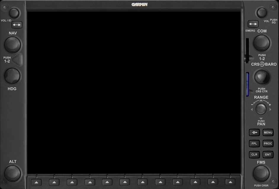
PFD_RANGE_INCR |
Zoom out on the PFD inset map. |
|
PFD_RANGE_DECR |
Zoom in on the PFD inset map |
|
PFD_RANGE_PRESS |
Activate the pan pointer cursor on the
PFD inset map. |
|
PFD_RANGE_PAN_UP |
Moves the pan pointer cursor in the
specified direction on the PFD inset map. |
|
PFD_RANGE_PAN_DOWN |
|
PFD_RANGE_PAN_LEFT |
|
PFD_RANGE_PAN_RIGHT |
|
PFD_DIRECT_TO |
Press the Direct-To button on the PFD. |
|
PFD_MENU |
Press the MENU button on the PFD. |
|
PFD_FPL |
Press the FPL button to view the flight
plan window on the PFD |
|
PFD_PROC |
Press the PROC button on the PFD to
select procedures like approaches, SIDs and STARs. |
|
PFD_CLR |
Press the CLR button on the PFD to clear
screens, erase inputs, etc. |
|
PFD_ENT |
Press the ENT button on the PFD to accept
the active field's input. |
|
PFD_LARGE_FMS_INCR |
CW turn of the large FMS knob on the PFD
that moves the input cursor to the next field or the next
character in the active field. |
|
PFD_LARGE_FMS_DECR |
CCW turn of the large FMS knob on the PFD
that moves the input cursor to the previous field or the previous
character in the active field. |
|
PFD_SMALL_FMS_INCR |
CW turn of the small FMS knob on the PFD
that highlights the next item in a list, or changes the selected
character in a field to the next character in alphabetic/numeric
sequence. |
|
PFD_SMALL_FMS_DECR |
CCW turn of the small FMS knob on the PFD
that highlights the previous item in a list, or changes the
selected character in a field to the previous character in
alphabetic/numeric sequence. |
|
PFD_SMALL_FMS_PRESS |
Activates or de-activates the highlight
box around a field on the PFD. |
|
PFD_SOFTKEY_1 |
Press the associated softkey
across the bottom of the PFD |
|
PFD_SOFTKEY_2 |
|
PFD_SOFTKEY_3 |
|
PFD_SOFTKEY_4 |
|
PFD_SOFTKEY_5 |
|
PFD_SOFTKEY_6 |
|
PFD_SOFTKEY_7 |
|
PFD_SOFTKEY_8 |
|
PFD_SOFTKEY_9 |
|
PFD_SOFTKEY_10 |
|
PFD_SOFTKEY_11 |
|
PFD_SOFTKEY_12 |
MFD Controls
 |
|
MFD_NAV_FREQ_TOGGLE |
Toggles the active and standby
frequencies in the selected NAV radio on the MFD. |
|
MFD_LARGE_NAV_INCR |
CW turn of the large NAV knob that
increases megahertz in the selected NAV radio on the MFD. |
|
MFD_LARGE_NAV_DECR |
CCW turn of the large NAV knob that
decreases megahertz in the selected NAV radio on the MFD. |
|
MFD_SMALL_NAV_INCR |
CW turn of the small NAV knob that
increases kilohertz in the selected NAV radio on the MFD. |
|
MFD_SMALL_NAV_DECR |
CCW turn of the small NAV knob that
decreases kilohertz in the selected NAV radio on the MFD. |
|
MFD_SMALL_NAV_PRESS |
Press the NAV knob which changes the
selected NAV radio on the MFD, and moves the tuning cursor between
NAV1 and NAV2. |
|
MFD_COM_FREQ_TOGGLE |
Toggles the active and standby
frequencies in the selected COM radio on the MFD. |
|
MFD_COM_FREQ_TOGGLE_HOLD |
Simulates the pressing and holding of
the COM frequency toggle button on the MFD which forces the COM1
radio to tune frequency to 121.5. |
|
MFD_LARGE_COM_INCR |
CW turn of the large COM knob that
increases megahertz in the selected COM radio on the MFD. |
|
MFD_LARGE_COM_DECR |
CCW turn of the large COM knob that
decreases megahertz in the selected COM radio on the MFD. |
|
MFD_SMALL_COM_INCR |
CW turn of the small COM knob that
increases kilohertz in the selected COM radio on the MFD. |
|
MFD_SMALL_COM_DECR |
CCW turn of the small COM knob that
decreases kilohertz in the selected COM radio on the MFD. |
|
MFD_SMALL_COM_PRESS |
Press the COM knob which changes the
selected COM radio on the MFD, and moves the tuning cursor between
COM1 and COM2. |
|
MFD_BARO_INCR |
CW turn of the "baro" knob that
increases the value in the Kohlsman window. |
|
MFD_BARO_DECR |
CW turn of the "baro" knob that
increases the value in the Kohlsman window. |
|
MFD_RANGE_INCR |
Zoom out on the MFD map. |
|
MFD_RANGE_DECR |
Zoom in on the MFD map |
|
MFD_RANGE_PRESS |
Activate the pan pointer cursor on the
MFD map. |
|
MFD_RANGE_PAN_UP |
Moves the pan pointer cursor in the
specified direction on the MFD map. The NW, SW, NE, SE
options do not move the pointer in the magnetic directions
northwest, soutwest, etc, but rather, NW means the top left of the
screen, SE means the bottom right of the screen, etc., regardless
of map orientation. |
|
MFD_RANGE_PAN_DOWN |
|
MFD_RANGE_PAN_LEFT |
|
MFD_RANGE_PAN_RIGHT |
|
MFD_RANGE_PAN_NW |
|
MFD_RANGE_PAN_SW |
|
MFD_RANGE_PAN_NE |
|
MFD_RANGE_PAN_SE |
|
MFD_RANGE_PAN_HOLD |
Repeat the last pan pointer cursor move
event to simulate holding the knob in place. Use this event,
instead of repeating the same event, to allow cursor motion
accelaration to occur as the knob is held in the pan position. |
|
MFD_RANGE_PAN_RELEASE |
Stop the repeating of pan pointer cursor
move events that were started with the PAN_HOLD event above. |
|
MFD_DIRECT_TO |
Press the Direct-To button on the MFD. |
|
MFD_MENU |
Press the MENU button on the MFD |
|
MFD_FPL |
Press the FPL button to view the flight
plan window on the MFD. |
|
MFD_PROC |
Press the PROC button on the MFD to
select procedures like approaches, SIDs and STARs. |
|
MFD_CLR |
Press the CLR button on the MFD to clear
screens, erase inputs, etc. |
|
MFD_CLR_HOLD |
Simulate the CLR knob having been held
for 3 seconds, which forces the MFD to return to the NAV page
group, page #1 no matter what is on the screen. |
|
MFD_ENT |
Press the ENT button on the MFD to accept
the active field's input. |
|
MFD_LARGE_FMS_INCR |
CW turn of the large FMS knob on the MFD
that moves the input cursor to the next field or the next
character in the active field. |
|
MFD_LARGE_FMS_DECR |
CCW turn of the large FMS knob on the
MFD that moves the input cursor to the previous field or the
previous character in the active field. |
|
MFD_SMALL_FMS_INCR |
CW turn of the small FMS knob on the MFD
that highlights the next item in a list, or changes the selected
character in a field to the next character in alphabetic/numeric
sequence. |
|
MFD_SMALL_FMS_DECR |
CCW turn of the small FMS knob on the
MFD that highlights the previous item in a list, or changes the
selected character in a field to the previous character in
alphabetic/numeric sequence. |
|
MFD_SMALL_FMS_PRESS |
Activates or de-activates the highlight
box around a field on the MFD. |
|
MFD_SOFTKEY_1 |
Press the associated softkey across the
bottom of the MFD |
|
MFD_SOFTKEY_2 |
|
MFD_SOFTKEY_3 |
|
MFD_SOFTKEY_4 |
|
MFD_SOFTKEY_5 |
|
MFD_SOFTKEY_6 |
|
MFD_SOFTKEY_7 |
|
MFD_SOFTKEY_8 |
|
MFD_SOFTKEY_9 |
|
MFD_SOFTKEY_10 |
|
MFD_SOFTKEY_11 |
|
MFD_SOFTKEY_12 |
RFD Controls
Note that only certain aircraft styles support the presence of the
"Right Flight Display" aka "Co-pilot PFD". Only the
Mustang, Caravan, Meridian, Matrix, and Mirage configurations will
allow the RFD to function without any special steps. In addition, some features
of the RFD rely on the presence of customized aircraft-specific
systems that are available only for professional simulators.
For this reason, do not attempt to use the RFD.
unless you are specifically advised to do so by technical support.
See also the aircraft-specific setting "EnableRFD" earlier in this
document.
|
|
RFD_NAV_FREQ_TOGGLE |
Toggles the active and standby
frequencies in the selected NAV radio on the RFD. |
|
RFD_LARGE_NAV_INCR |
CW turn of the large NAV knob that
increases megahertz in the selected NAV radio on the RFD |
|
RFD_LARGE_NAV_DECR |
CCW turn of the large NAV knob that
decreases megahertz in the selected NAV radio on the RFD. |
|
RFD_SMALL_NAV_INCR |
CW turn of the small NAV knob that
increases kilohertz in the selected NAV radio on the RFD. |
|
RFD_SMALL_NAV_DECR |
CCW turn of the small NAV knob that
decreases kilohertz in the selected NAV radio on the RFD. |
|
RFD_SMALL_NAV_PRESS |
Press the NAV knob which changes the
selected NAV radio on the RFD, and moves the tuning cursor between
NAV1 and NAV2. |
|
RFD_COM_FREQ_TOGGLE |
Toggles the active and standby
frequencies in the selected COM radio on the RFD. |
|
RFD_COM_FREQ_TOGGLE_HOLD |
Simulates the pressing and holding of
the COM frequency toggle button on the RFD which forces the COM1
radio to tune frequency to 121.5. |
|
RFD_LARGE_COM_INCR |
CW turn of the large COM knob that
increases megahertz in the selected COM radio on the RFD. |
|
RFD_LARGE_COM_DECR |
CCW turn of the large COM knob that
decreases megahertz in the selected COM radio on the RFD. |
|
RFD_SMALL_COM_INCR |
CW turn of the small COM knob that
increases kilohertz in the selected COM radio on the RFD. |
|
RFD_SMALL_COM_DECR |
CCW turn of the small COM knob that
decreases kilohertz in the selected COM radio on the RFD. |
|
RFD_SMALL_COM_PRESS |
Press the COM knob which changes the
selected COM radio on the RFD, and moves the tuning cursor between
COM1 and COM2. |
|
RFD_CRS_INCR |
CW turn of the course knob on the RFD
which, in authorized conditions, changes the green course pointer
on the HSI. |
|
RFD_CRS_DECR |
CCW turn of the course knob on the RFD
which, in authorized conditions, changes the green course pointer
on the HSI. |
|
RFD_CRS_PRESS |
Press the course knob on the RFD which,
in authorized conditions, auto-slews the course pointer TO the
station that is the active NAV source. |
|
RFD_BARO_INCR |
CW turn of the "baro" knob that increases
the value in the Kohlsman window. |
|
RFD_BARO_DECR |
CW turn of the "baro" knob that increases
the value in the Kohlsman window. |
|
RFD_RANGE_INCR |
Zoom out on the RFD map. |
|
RFD_RANGE_DECR |
Zoom in on the RFD map |
|
RFD_RANGE_PRESS |
Activate the pan pointer cursor on the
RFD map. |
|
RFD_RANGE_PAN_UP |
Moves the pan pointer cursor in the
specified direction on the RFD inset map. |
|
RFD_RANGE_PAN_DOWN |
|
RFD_RANGE_PAN_LEFT |
|
RFD_RANGE_PAN_RIGHT |
|
RFD_DIRECT_TO |
Press the Direct-To button on the RFD. |
|
RFD_MENU |
Press the MENU button on the RFD. |
|
RFD_FPL |
Press the FPL button to view the flight
plan window on the RFD. |
|
RFD_PROC |
Press the PROC button on the RFD to
select procedures like approaches, SIDs and STARs. |
|
RFD_CLR |
Press the CLR button on the RFD to clear
screens, erase inputs, etc. |
|
RFD_ENT |
Press the ENT button on the RFD to
accept the active field's input. |
|
RFD_LARGE_FMS_INCR |
CW turn of the large FMS knob on the RFD
that moves the input cursor to the next field or the next
character in the active field. |
|
RFD_LARGE_FMS_DECR |
CCW turn of the large FMS knob on the
RFD that moves the input cursor to the previous field or the
previous character in the active field. |
|
RFD_SMALL_FMS_INCR |
CW turn of the small FMS knob on the RFD
that highlights the next item in a list, or changes the selected
character in a field to the next character in alphabetic/numeric
sequence. |
|
RFD_SMALL_FMS_DECR |
CCW turn of the small FMS knob on the
RFD that highlights the previous item in a list, or changes the
selected character in a field to the previous character in
alphabetic/numeric sequence. |
|
RFD_SMALL_FMS_PRESS |
Activates or de-activates the highlight
box around a field on the RFD. |
|
RFD_SOFTKEY_1 |
Press the associated softkey across the
bottom of the RFD |
|
RFD_SOFTKEY_2 |
|
RFD_SOFTKEY_3 |
|
RFD_SOFTKEY_4 |
|
RFD_SOFTKEY_5 |
|
RFD_SOFTKEY_6 |
|
RFD_SOFTKEY_7 |
|
RFD_SOFTKEY_8 |
|
RFD_SOFTKEY_9 |
|
RFD_SOFTKEY_10 |
|
RFD_SOFTKEY_11 |
|
RFD_SOFTKEY_12 |
Audio Panel Controls

AUDIO
(GMA-1347) |
|
AUDIO_TRANSMIT_COM1 |
Transmit and Receive on COM1. |
|
AUDIO_MONITOR_COM1 |
Listen to COM1 even if COM2 is selected
for transmit. |
|
AUDIO_TRANSMIT_COM2 |
Transmit and Receive on COM2. |
|
AUDIO_MONITOR_COM2 |
Listen to COM2 even if COM1 is selcted
for transmit. |
|
AUDIO_TRANSMIT_COM3 |
Transmit and Receive on COM3. (Not useful
in FSX or P3D because the sim doesn't have a COM3. |
|
AUDIO_MONITOR_COM3 |
Listen to COM3 even if COM3 is not
selected for transmit. (Not useful in FSX or P3D since the sim
doesn't have a COM3) |
|
AUDIO_COM12 |
Pilot transmits and receives COM1,
copilot transmits and receives COM2. |
|
AUDIO_TEL |
Only turns on the associated LED. |
|
AUDIO_PA |
Only turns on the associated LED. |
|
AUDIO_SPKR |
Only turns on the associated LED. |
|
AUDIO_MARKER_MUTE |
Silence the outer/middle/inner marker
during an approach. |
|
AUDIO_HI_SENS |
Switch the marker to high-sensitivity
mode. |
|
AUDIO_MONITOR_NAV1 |
Listen to NAV1 audio. |
|
AUDIO_MONITOR_NAV2 |
Listen to NAV2 audio. |
|
AUDIO_MONITOR_DME |
Activates Morse code identifier for the
DME being received. |
|
AUDIO_MONITOR_ADF |
Activates Morse code identifer for the
NDB being received. |
|
AUDIO_MONITOR_AUX |
Listen to the AUX input in the cockpit. |
|
AUDIO_MANUAL_SQUELCH |
Only turns on the associated LED. |
|
AUDIO_PLAY |
Only turns on the associated LED. |
|
AUDIO_ISOLATE_PILOT |
For future use, isolates the intercom to
the pilot only. |
|
AUDIO_ISOLATE_COPILOT |
For future use, isolates the intercom to
the copoilot only. |
|
AUDIO_ACTIVATE_REVERSIONARY |
Activates reversionary mode so the PFD
and MFD show a consolidated flight instrument and engine
instrument display. |
|
AUDIO_ACTIVATE_REVERSIONARY2 |
|
Autopilot GFC-700 AFCS
 |
|
AFCS_1 |
These events are intended for the GFC-700
autopilot buttons mounted on the GDU-1040 units.
They are not intended for autopilot controllers like the
AP_CONTROLLER_CESSNA or AP_CONTROLLER_CIRRUS. For
those, see the events starting with KEYPAD_AFCS_*** below.
These numbers, 1 thru 12, represent the 12 possible
autopilot control buttons on the bezel, from left to right, top to
bottom. Most aircraft assign the default functions to
these buttons, as described in the "Named Equivalents" list below
this group. However, some aircraft models rearrange the
buttons so that they are not in the default sequence.
These numbered versions are intended for hardware that has a
single control interface for multiple airplanes. In these
cases the G1000 software itself will decide what function that a
particular button position should execute.
|
|
AFCS_2 |
|
AFCS_3 |
|
AFCS_4 |
|
AFCS_5 |
|
AFCS_6 |
|
AFCS_7 |
|
AFCS_8 |
|
AFCS_9 |
|
AFCS_10 |
|
AFCS_11 |
|
AFCS_12 |
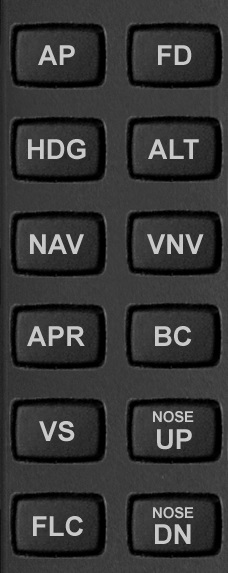
Named Equivalents for AFCS_1
thru AFCS_12
|
|
AFCS_AP |
These events are intended
for the GFC-700 autopilot buttons mounted on the GDU-1040 units.
They are equivalent in function to the set of numbered AFCS events
above. However, these events represent specific autopilot
functions, with no regard for the order of the buttons on the
bezel.
These are not intended for autopilot controllers
like the AP_CONTROLLER_CESSNA or AP_CONTROLLER_CIRRUS. For
those, see the events starting with KEYPAD_AFCS_*** below. |
|
AFCS_FD |
|
AFCS_HDG |
|
AFCS_ALT |
|
AFCS_NAV |
|
AFCS_VNV |
|
AFCS_APR |
|
AFCS_BC |
|
AFCS_VS |
|
AFCS_UP |
|
AFCS_FLC |
|
AFCS_DN |
| Additional Named AFCS Events
for Buttons Not Typically on the GDU-1040 Units |
|
AFCS_YD |
These are additional GFC-700
autopilot events for knobs that buttons that are usually not on
the GDU-1040 bezel. (The YD button sometimes does
appear on the bezel in some cases, though).
The Yoke Disconnect, and Go Around buttons are
listedin this section for convenience even though they don't
typically appear on controller gauges. |
|
AFCS_YOKE_DISCONNECT |
|
AFCS_GA |
AFCS buttons for Autopilot Controllers
These trigger the same behavior as
AFCS1-12 and their named equivalents, plus some additional
functions that typically appear on autopiot controllers. |
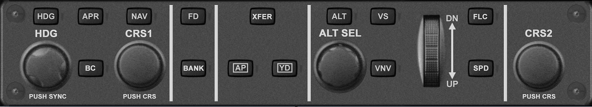
AP_CONTROLLER_CESSNA
(GMC-710) |
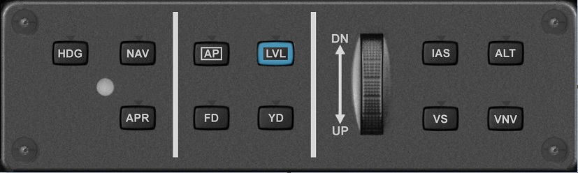
AP_CONTROLLER_CIRRUS
(GMC-305) |
|
|
AFCS_LVL |
Toggles the wing leverler on and off. Same as KEYPAD_AFCS_LVL |
|
AFCS_XFER |
Toggles primary AP control between pilot and copilot. |
|
AFCS_BANK |
Toggles bank-hold mode on and off. |
|
AFCS_SPD |
Toggles speed-hold mode on and off. |
|
AFCS_CRS1_INCR |
Turn the CRS1 knob to the right (increase) |
|
AFCS_CRS1_DECR |
Turn the CRS1 knob to the left (decrease) |
|
AFCS_CRS1_PRESS |
Press the CRS1 knob (sync) |
|
AFCS_CRS2_INCR |
Turn the CRS2 knob to the right (increase) |
|
AFCS_CRS2_DECR |
Turn the CRS2 knob to the left (decrease) |
|
AFCS_CRS2_PRESS |
Press the CRS2 knob (sync) |
|
KEYPAD_AFCS_AP |
Toggles autopilot control of the aircraft
on and off. |
|
KEYPAD_AFCS_FD |
Toggles the flight director on/off |
|
KEYPAD_AFCS_HDG |
Toggles HDG mode on and off in the
GFC-700 autopilot. |
|
KEYPAD_AFCS_ALT |
Toggles ALT (altitude hold) mode on and
off in the GFC-700 autopilot. |
|
KEYPAD_AFCS_NAV |
Toggles NAV mode on and off
in the GFC-700 autopilot. |
|
KEYPAD_AFCS_VNV |
Toggles VNAV mode on and off in the
GFC-700 autopilot. |
|
KEYPAD_AFCS_APR |
Toggles Approach Mode on and off in the
GFC-700 autopilot. |
|
KEYPAD_AFCS_BC |
Toggles Backcourse mode on and off in the
GFC-700 autopilot. |
|
KEYPAD_AFCS_VS |
Toggles Vertical Speed mode on and off in
the GFC-700 autopilot. |
|
KEYPAD_AFCS_UP |
Pitch up, or decrease selected FLC
airspeed in the GFC-700 autopilot. |
|
KEYPAD_AFCS_FLC |
Toggles Flight Level Change mode on and
off in the GFC-700 autopilot. |
|
KEYPAD_AFCS_DN |
Pitch down, or increase selected FLC
airspeed in the GFC-700 autopilot |
|
KEYPAD_AFCS_YD |
Toggles Yaw Damper on and off in the
GFC-700 autopilot. Only available in certain aircraft. Same as AFCS_YD. |
|
KEYPAD_AFCS_LVL |
Toggles the wing leveller on and off. Same as AFCS_LVL. |
Events for Keypads
(READYPAD, CIRRUSPAD, MUSTANGPAD)
No keypads have all the
functions at the same time. Refer to the keypad layouts. |

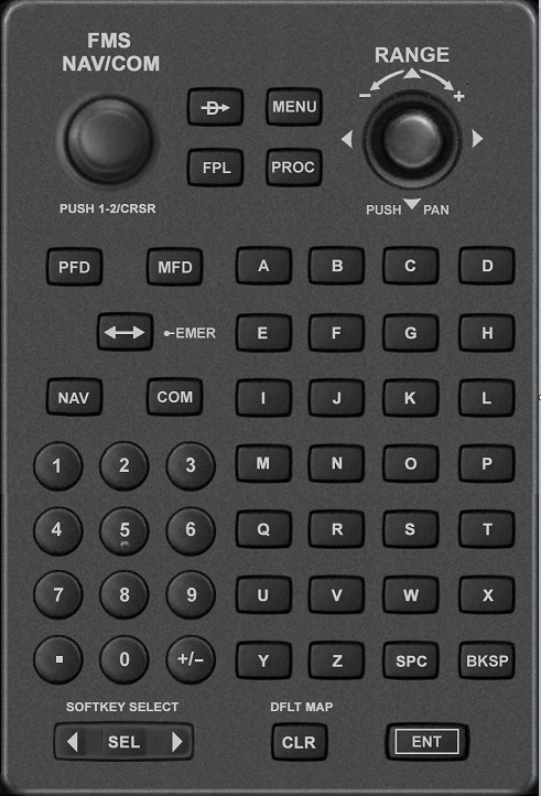
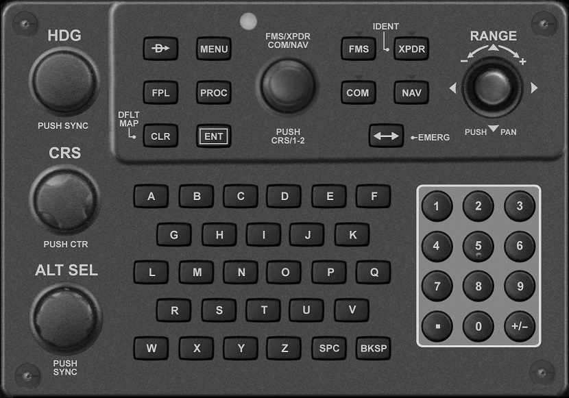
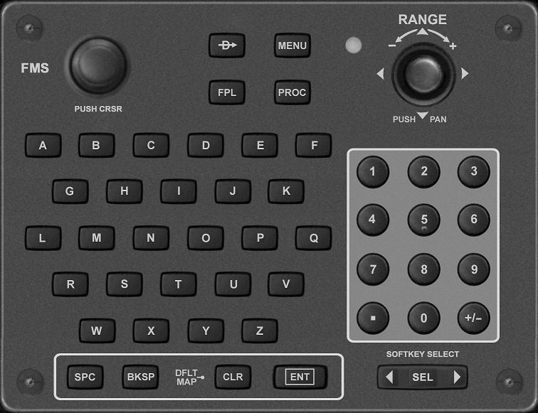
READYPAD
(GCU-476) |
CIRRUSPAD
(GCU-478) |

MUSTANGPAD
(GCU-475) |
|
|
KEYPAD_HDG_INCR |
CW turn of the heading knob on a keypad. |
|
KEYPAD_HDG_DECR |
CCW turn of the heading knob on a
keypad. |
|
KEYPAD_HDG_PRESS |
Presses the heading knob on a keypad. |
|
KEYPAD_CRS_INCR |
CW turn of the course knob on a keypad
which, in authorized conditions, changes the green course pointer
on the HSI for the selected NAV source. |
|
KEYPAD_CRS_DECR |
CCW turn of the course knob on a keypad
which, in authorized conditions, changes the green course pointer
on the HSI for the selected NAV source.
|
|
KEYPAD_CRS_PRESS |
Press the course knob on a keypad which,
in authorized conditions, auto-slews the course pointer TO the
station that is the active NAV source.
|
|
KEYPAD_ALT_INCR |
CW turn of the small ALT knob that
increases the altimeter bug in hundred-foot increments. This
keypad version of this function includes acceleration so faster
turns adjust the altitude faster, which is different than how the
PFD and MFD operate. |
|
KEYPAD_ALT_DECR |
CCW turn of the small ALT knob that
decreases the altimeter bug in hundred-foot increments. This
keypad version of this function includes acceleration so faster
turns adjust the altitude faster, which is different than how the
PFD and MFD operate. |
|
KEYPAD_ALT_PRESS |
Presses that small ALT knob that sets
the altimeter bug to the current altitude. Only available in
certain aircraft. |
|
KEYPAD_DIRECT_TO |
Press the Direct-To button on a keypad. |
|
KEYPAD_MENU |
Press the MENU button on a keypad. |
|
KEYPAD_FPL |
Press the FPL button to view the flight
plan window on a keypad |
|
KEYPAD_PROC |
Press the PROC button on a keypad to
select procedures like approaches, SIDs and STARs. |
|
KEYPAD_CLR |
Press the CLR button on a keypad to
clear screens, erase inputs, etc. |
|
KEYPAD_CLR_HOLD |
Simulate the CLR knob having been held
for 3 seconds, which forces the MFD to return to the NAV page
group, page #1 no matter what is on the screen. |
|
KEYPAD_ENT |
Press the ENT button on a keypad to
accept the active field's input. |
|
KEYPAD_LARGE_FMS_INCR |
CW turn of the large FMS knob on a
keypad that moves the input cursor to the next field or the next
character in the active field. |
|
KEYPAD_LARGE_FMS_DECR |
CCW turn of the large FMS knob on a
keypad that moves the input cursor to the previous field or the
previous character in the active field. |
|
KEYPAD_SMALL_FMS_INCR |
CW turn of the small FMS knob on a
keypad that highlights the next item in a list, or changes the
selected character in a field to the next character in
alphabetic/numeric sequence. |
|
KEYPAD_SMALL_FMS_DECR |
CCW turn of the small FMS knob on a
keypad that highlights the previous item in a list, or changes the
selected character in a field to the previous character in
alphabetic/numeric sequence. |
|
KEYPAD_SMALL_FMS_PRESS |
Activates or de-activates the highlight
box around a field on the selected display unit. |
|
KEYPAD_SELECT_FMS |
Directs kepad input to FMS-related fields |
|
KEYPAD_SELECT_XPDR |
Directs keypad input to the transponder
field. |
|
KEYPAD_SELECT_PFD |
Directs keypad input to the fields on the
PFD |
|
KEYPAD_SELECT_MFD |
Directs keypad input to the fields on the
MFD |
|
KEYPAD_SELECT_COM |
Directs keypad input to the COM fields. |
|
KEYPAD_SELECT_NAV |
Directs keypad input to the NAV fields. |
|
KEYPAD_FREQ_TOGGLE |
Toggles the active and standby frequency
on the selected COM or NAV radio. |
|
KEYPAD_FREQ_TOGGLE_HOLD |
Simulates the pressing and holding of
the frequency toggle button on a keypad which forces the COM1
radio to tune frequency to 121.5. |
|
KEYPAD_RANGE_INCR |
Zoom out on the map on the selected
display unit. |
|
KEYPAD_RANGE_DECR |
Zoom in on the map on the selected
display unit. |
|
KEYPAD_RANGE_PRESS |
Activate the pan pointer cursor on the
map on the selected display unit. |
|
KEYPAD_RANGE_PAN_UP |
Moves the pan pointer cursor in the
specified direction on the selected map. The NW, SW, NE, SE
options do not move the pointer in the magnetic directions
northwest, soutwest, etc, but rather, NW means the top left of the
screen, SE means the bottom right of the screen, etc., regardless
of map orientation. |
|
KEYPAD_RANGE_PAN_DOWN |
|
KEYPAD_RANGE_PAN_LEFT |
|
KEYPAD_RANGE_PAN_RIGHT |
|
KEYPAD_RANGE_PAN_NW |
|
KEYPAD_RANGE_PAN_SW |
|
KEYPAD_RANGE_PAN_NE |
|
KEYPAD_RANGE_PAN_SE |
|
KEYPAD_RANGE_PAN_HOLD |
Repeat the keypad's last pan pointer
cursor move event to simulate holding the knob in place. Use this
event, instead of repeating the same event, to allow cursor motion
accelaration to occur as the knob is held in the pan position. |
|
KEYPAD_RANGE_PAN_RELEASE |
Stop the repeating the keypad's last pan
pointer cursor move events that were started with the PAN_HOLD
event above. |
|
KEYPAD_A |
Events for individual
letters and numbers on the keypad. |
|
KEYPAD_B |
|
KEYPAD_C |
|
KEYPAD_D |
|
KEYPAD_E |
|
KEYPAD_F |
|
KEYPAD_G |
|
KEYPAD_H |
|
KEYPAD_I |
|
KEYPAD_J |
|
KEYPAD_K |
|
KEYPAD_L |
|
KEYPAD_M |
|
KEYPAD_N |
|
KEYPAD_O |
|
KEYPAD_P |
|
KEYPAD_Q |
|
KEYPAD_R |
|
KEYPAD_S |
|
KEYPAD_T |
|
KEYPAD_U |
|
KEYPAD_V |
|
KEYPAD_W |
|
KEYPAD_X |
|
KEYPAD_Y |
|
KEYPAD_Z |
|
KEYPAD_0 |
|
KEYPAD_1 |
|
KEYPAD_2 |
|
KEYPAD_3 |
|
KEYPAD_4 |
|
KEYPAD_5 |
|
KEYPAD_6 |
|
KEYPAD_7 |
|
KEYPAD_8 |
|
KEYPAD_9 |
|
KEYPAD_DECIMAL |
|
KEYPAD_PLUS_MINUS |
|
KEYPAD_SPC |
|
KEYPAD_BKSP |
|
KEYPAD_SOFTKEY_SELECT_LEFT |
Moves a highlight box to the left in the
softkey section of the selected display unit. |
|
KEYPAD_SOFTKEY_SELECT_RIGHT |
Moves a highlight box to the right in the
softkey section of the selected display unit. |
|
KEYPAD_SOFTKEY_PRESS |
Presses the highlighted softkey on the
selected display unit. |
| "SELECTED UNIT" controls -
Directed at whichever display unit (PFD, MFD, or RFD) that was
last touched. |
|
CURRENT_INNER_FMS_INCR |
(obsolete) Factory-set to the
= key |
|
CURRENT_INNER_FMS_DECR |
(obsolete) Factory set to the DASH key (DASH is a
keyword) |
|
CURRENT_OUTER_FMS_INCR |
(obsolete) Factory-set to SHIFT+= |
|
CURRENT_OUTER_FMS_DECR |
(obsolete) Factory set to SHIFT+DASH |
|
CURRENT_ENT |
Factory set to ENTER (ENTER is a keyword) |
G1000 Failures - *TOGGLE* Failure State
Each time these events are fired, they toggle the state of the
respective failure between FAILED and NOT FAILED. |
|
FAIL_COM1_TOGGLE |
Toggles the failure state of the COM1
radio. |
|
FAIL_COM2_TOGGLE |
Toggles the failure state of the COM2
radio. |
|
FAIL_NAV1_TOGGLE |
Toggles the failure state of the NAV1
radio. |
|
FAIL_NAV2_TOGGLE |
Toggles the vailue state of the NAV 2
radio. |
|
FAIL_AHRS_TOGGLE |
Toggles failure state of the Attitude,
Heading and Reference System. Intended for aircraft with
only one AHRS LRU (line replacable unit). Same as
FAIL_AHRS_1_TOGGLE. |
|
FAIL_AHRS_1_TOGGLE |
Toggles the failure state of AHRS #1 |
|
FAIL_AHRS_2_TOGGLE |
Toggles the failure state of AHRS #2 |
|
FAIL_HDG_TOGGLE |
Failes the magnetometer and its sensor. |
|
FAIL_ADC_TOGGLE |
Toggles the failure state of the Air Data
Computer LRU (line replaceable unit). Intended for aircraft
one only one ADC. Same as FAIL_ADC_1_TOGGLE |
|
FAIL_ADC_1_TOGGLE |
Toggles the failure state of ADC #1 |
|
FAIL_ADC_2_TOGGLE |
Toggles the failure state of ADC #2 |
|
FAIL_IAU_TOGGLE |
Toggles the failure state of both
Integrated Avionics Units inside the GDU-1040 displays.
. |
|
FAIL_IAU_1_TOGGLE |
Toggles the failure state of IAU #1 |
|
FAIL_IAU_2_TOGGLE |
Toggles the failure state of IAU #2 |
|
FAIL_EAU_TOGGLE |
Toggles the failure state of the Engine
and Airframe LRU (line replaceable unit). |
|
FAIL_XPDR_TOGGLE |
Toggles the failure state of the
transponder. |
|
FAIL_PFD_TOGGLE |
Toggles the failure state of the PFD
display. |
|
FAIL_MFD_TOGGLE |
Toggles the failure state of the MFD
display. |
|
FAIL_RFD_TOGGLE |
Toggles the failure state of the RFD
display. |
|
FAIL_TRAFFIC_TOGGLE |
Toggles the failure state of the traffic
information system. |
|
FAIL_DME_TOGGLE |
Toggles the failure state of the DME
radio. |
|
FAIL_GS_TOGGLE |
Toggles the failure state of the
glideslope receiver. |
|
FAIL_GPS_TOGGLE |
Toggles a failure of the GPS systems in
the G1000. |
|
FAIL_RAIM_TOGGLE |
Toggles a failure of GPS satellite
redundancy. |
|
FAIL_TAWS_TOGGLE |
Toggles a failure of the terrain
awareness and warning system. |
|
FAIL_AP_CONTROLLER_TOGGLE |
Toggles a failure of the autopilot
controller panel. |
|
FAIL_AP_SERVOS_TOGGLE |
Toggles a failure of the servos that
manipulate the control surfaces during autopilot use. |
|
FAIL_AP_PITCH_TOGGLE |
Toggles a failure of the pitch servos
that manipulate the elevator during autopilot use. |
|
FAIL_AP_ROLL_TOGGLE |
Toggles a failure of the roll servos that
manipulate the ailerons during autopilot use. |
|
FAIL_AP_PITCH_TRIM_TOGGLE |
Toggles a failure of the autopilot pitch
trim control |
|
FAIL_AP_YAW_TOGGLE |
Toggles a failure of the yaw damper. |
|
FAIL_AP_MISTRIM_UP_TOGGLE |
Toggles a message on the PFD for mistrim
in the pitch axis. |
|
FAIL_AP_MISTRIM_DOWN_TOGGLE |
Toggles a message on the PFD for mistrim
in the pitch axis. |
|
FAIL_AP_MISTRIM_AILERON_LEFT_TOGGLE |
Toggles a message on the PFD for mistrim
in the roll axis. |
|
FAIL_AP_MISTRIM_AILERON_RIGHT_TOGGLE |
Toggles a message on the PFD for mistrim
in the roll axis |
|
FAIL_AP_MISTRIM_RUDDER_LEFT_TOGGLE |
Toggles a message on the PFD for mistrim
in the yaw axis. |
|
FAIL_AP_MISTRIM_RUDDER_RIGHT_TOGGLE |
Toggles a message on the PFD for mistrim
in the yaw axis. |
|
FAIL_PFD_FAN_TOGGLE |
Toggles a message for a failure of the
PFD cooling fan. |
|
FAIL_MFD_FAN_TOGGLE |
Toggles a message for a failure of the
MFD cooling fan. |
|
FAIL_RFD_FAN_TOGGLE |
Toggles a message for a failure of
the RFD cooling fan. |
G1000 Failures - Direct
*SET* of Failure State
These failures must be fired via
SimConnect custom events, along with event data of 0 or 1 to set
failure state to FAILED or NOT failed.
An event
data value of 0 means not failed. An event data value
of 1 means failed. |
|
FAIL_COM1_SET |
SET version (instead of
TOGGLE version) of the same events described in the previous
block. See the TOGGLE versions in the prior block for
details.
The SET versions of these events require that the
event number be sent along with an event data value.
An
event data value of 0 clears the failure.
An event data
value of 1 causes the failure to occur. |
|
FAIL_COM2_SET |
|
FAIL_NAV1_SET |
|
FAIL_NAV2_SET |
|
FAIL_AHRS_SET |
|
FAIL_AHRS_1_SET |
|
FAIL_AHRS_2_SET |
|
FAIL_HDG_SET |
|
FAIL_ADC_SET |
|
FAIL_ADC_1_SET |
|
FAIL_ADC_2_SET |
|
FAIL_IAU_SET |
|
FAIL_IAU_1_SET |
|
FAIL_IAU_2_SET |
|
FAIL_EAU_SET |
|
FAIL_XPDR_SET |
|
FAIL_PFD_SET |
|
FAIL_MFD_SET |
|
FAIL_RFD_SET |
|
FAIL_TRAFFIC_SET |
|
FAIL_DME_SET |
|
FAIL_GS_SET |
|
FAIL_GPS_SET |
|
FAIL_RAIM_SET |
|
FAIL_TAWS_SET |
|
FAIL_AP_CONTROLLER_SET |
|
FAIL_AP_SERVOS_SET |
|
FAIL_AP_PITCH_SET |
|
FAIL_AP_ROLL_SET |
|
FAIL_AP_PITCH_TRIM_SET |
|
FAIL_AP_YAW_SET |
|
FAIL_AP_MISTRIM_UP_SET |
|
FAIL_AP_MISTRIM_DOWN_SET |
|
FAIL_AP_MISTRIM_AILERON_LEFT_SET |
|
FAIL_AP_MISTRIM_AILERON_RIGHT_SET |
|
FAIL_AP_MISTRIM_RUDDER_LEFT_SET |
|
FAIL_AP_MISTRIM_RUDDER_RIGHT_SET |
|
FAIL_PFD_FAN_SET |
|
FAIL_MFD_FAN_SET |
|
FAIL_RFD_FAN_SET |