The Aircraft Container System
Understanding FSX/P3D aircraft folder structure and panel configurations
In Microsoft-style flight simulators (FSX, ESP, Prepar3D), all aircraft specific files (except for the gauges themselves) are located in a folder generically called the aircraft container. The aircraft container is just a folder that resides deep inside the folder hierarchy of flight simulator.
Folder Structure Overview
The folder hierarchy itself can be a little daunting at times, but here's a simplified view of the folder structure showing where individual airplane container folders reside relative to the flight simulator root folder:
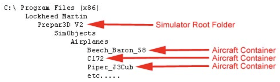
A Single Aircraft Container - The Cessna 172
For the remainder of this guide, we will focus on a single aircraft container using the Cessna 172 as our example. This means we will be looking at the C172 folder. To simplify our examples, we will not show the entire hierarchy of folders above the C172, but keep in mind that when looking at the C172 aircraft container folder, we are already several folder levels down into the simulator's folder structure.
Aircraft Container Folder Layout
Once you've seen one aircraft container folder, you've almost seen them all. The simulator software expects to find certain files and folders in every aircraft container, named exactly the same way every time. It doesn't matter if you're looking at a C172 or a Boeing 747, the exact same rules apply.
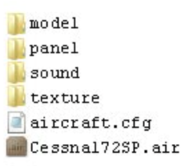
The aircraft.cfg File
The starting point for looking at any aircraft container is a file called the aircraft config, or aircraft.cfg file. It may not be at the top of the screen, but this is what flight simulator looks at first when detecting an aircraft.
The aircraft.cfg is a roadmap for everything else in the aircraft container. You can think of it like a sign outside a building that tells you what offices are inside. It's just a simple text file that can be viewed with Notepad or any other text editor program.
What Is an Aircraft Variation?
Let's imagine you have a Cessna 172 with a Bendix King radio and no GPS, and another Cessna 172 with twin GNS 430 units. That's two different variations of the same Cessna 172.
Flight simulator needs to know several things about these aircraft variations in order to be able to depict them in the simulated world. You don't need to know how to make these in order to modify cockpit panels, but a basic understanding of these components will help you understand how all the pieces fit together.
Aircraft Container Components
The Model
In order to show the exterior of an airplane in flight simulator, you need an aircraft model. Not surprisingly, there is a folder called model in the aircraft container folder.
The aircraft model is also called the 3D-model because it's a 3-dimensional object in flight simulator. Unlike a 2-dimensional image like a photograph, you can move "around" a 3D model. You can look at it from above, below, from the side, from the front, and so forth.
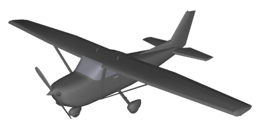
A model is designed by an artist using a CAD system (computer-aided design). For the most part, being an artist working as an aircraft modeler is like working with clay. There are no colors, no moving maps, no flight behavior, just a 3-dimensional shape floating in space.
Without any of the other parts of an aircraft container, a 3D model would look something like this:
The Texture
Next, we need a paint job. This is called the texture. (Notice the appropriately named texture folder in the aircraft container folder.) The texture is a bizarre looking thing by itself. It's just a collection of 2-dimensional images clumped together in a file.
A texture looks something like this:
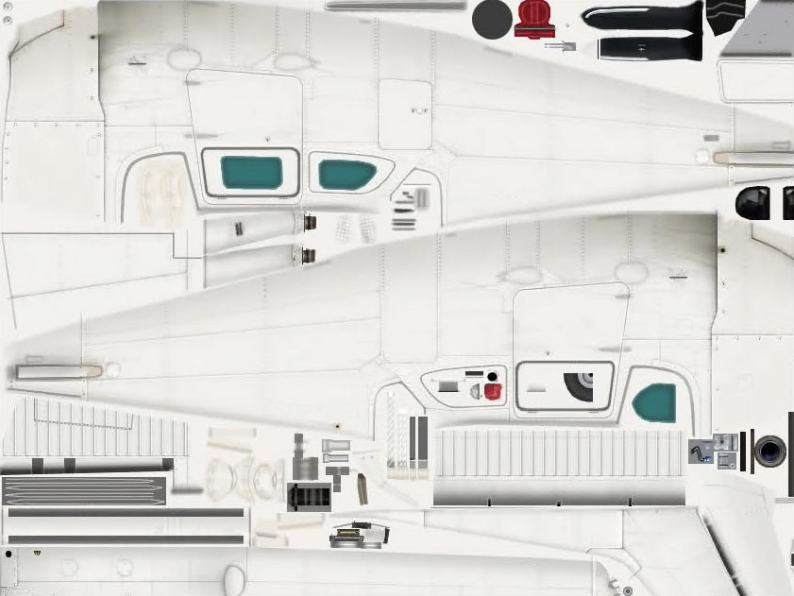
When the flight simulator does its magic, it "wraps" the 2-dimensional texture images around the 3D model so that you get a much more realistic looking airplane in the simulated world. This wrapping process is also called skinning or repainting by some artists.
Sounds
Next we need to think about whether this airplane makes any sound, right? Sound files that are specific to this airplane can be stored in the sound folder in the aircraft container. The sounds are just WAV files created by any number of tools used by sound editors.
Aerodynamics
So what about how this airplane flies? How fast does it go? How much does it weigh? This type of aerodynamic information is stored in a special type of flight simulator file called an air file. If you look at the example of the aircraft container folder, you will see a file named Cessna172SP.air. This file tells the simulator how this airplane is supposed to fly.
Control Panel
The only remaining thing to talk about is the aircraft control panel. Again, not surprisingly, there is a folder named panel in the aircraft container folder. This is where you'll spend most of your time when modifying cockpit control panels, and we will go into this in much more detail in the upcoming sections.
A Review - Pulling It All Together
So now you should be able to understand that the aircraft.cfg file tells flight simulator about what model, texture, sound, aerodynamic data, and control panel to use for any particular variation of an aircraft.
You don't need to worry about the details of how it all works. But you can start to recognize that a wide range of artists and skills are required just to get to this point. In many cases, the model is built by one person, the texture is built by a different person, the sounds are recorded and stored by a third person, and the aerodynamic information is collected and entered by yet another person.
But without the control panel (i.e. the panel folder in the aircraft container), you have nothing but a pretty airplane that flies around and makes some sounds in the simulated world, but with no instruments! No GPS, no radios, no compass, nothing! So now you see the massive importance of the panel folder.
The PANEL Folder in an Aircraft Container
Remember how the aircraft.cfg file was a roadmap to the rest of the aircraft container? Well, in that same way, a special file called the panel.cfg (panel config) is a roadmap to the instruments on the cockpit control panel.
The panel folder is useless without a panel config file, and every panel folder must contain a panel.cfg in order to function in flight simulator.
The panel.cfg File
The panel.cfg file is just a text file. It can be edited with Notepad. It is where the size and location of all instruments on the control panel are specified for both the 2D and 3D cockpits. The instruments are also called gauges, and we will use this word gauges to refer to every cockpit instrument. An airspeed indicator is a gauge. A GPS is a gauge. It may appear to be complicated at first, but you will find that once you understand the basic principles of gauge placement and how to read the gauge lines in the panel.cfg, you'll become quite confident in modifying panels for your own use.
Panel.cfg Structure
The panel.cfg file uses the same structure as the aircraft.cfg and many other configuration files in flight simulator. They are called INI files. All INI files have sections, and each section has a header. The header is the section name surrounded by square brackets:
The individual lines inside a section are a name, followed by an '=' sign:
Every panel.cfg file contains the following sections:
Understanding Gauge Lines
The 2D cockpit in any aircraft is Window #0, so the section in the panel.cfg that defines the 2D cockpit is named [Window00]. Any windows other than #0 are considered popup windows by flight simulator.
If you look at a panel.cfg file at its Window00 section, you will see among other things, a group of lines that start with gauge=
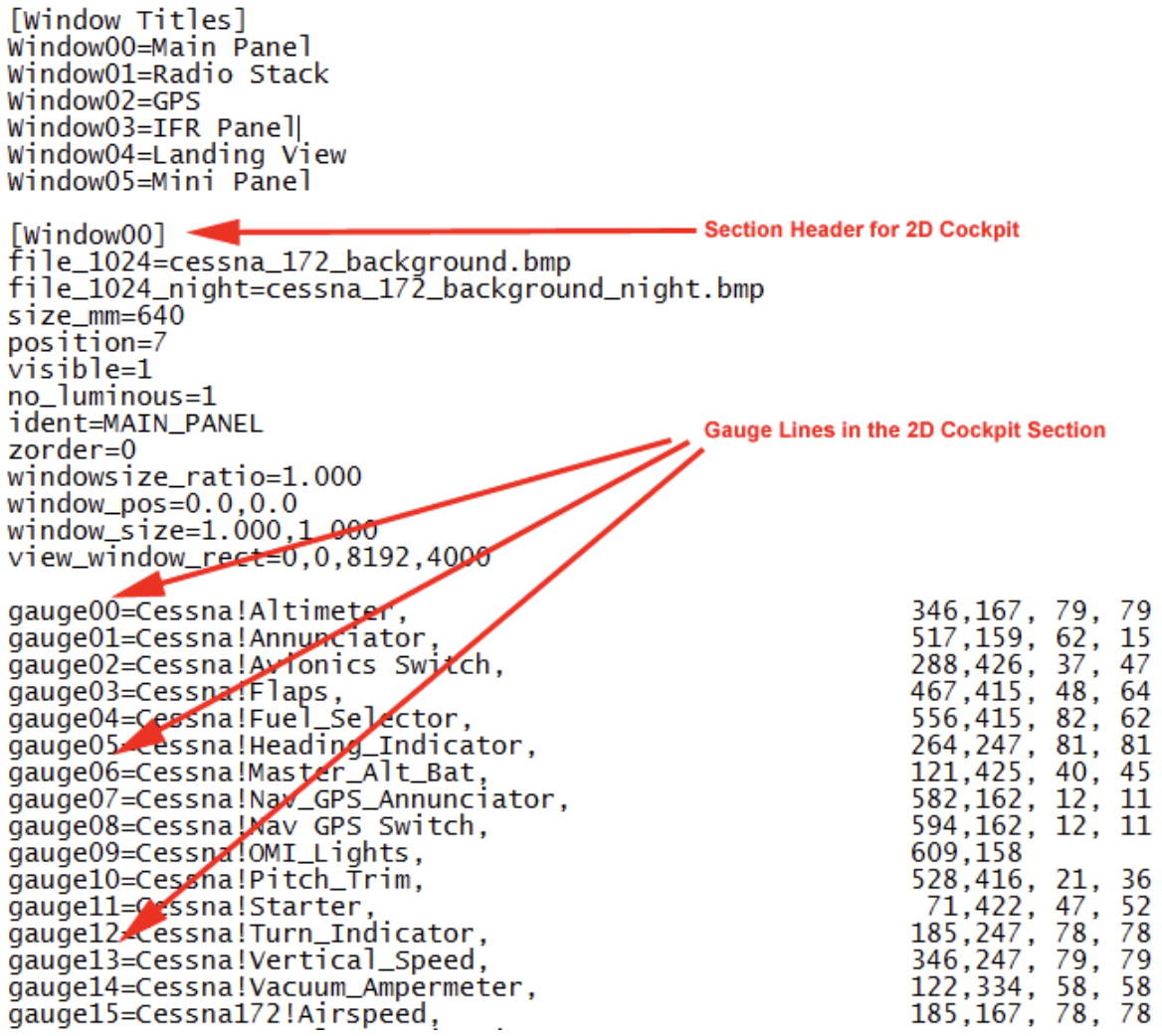
Each line that defines an individual instrument starts with the word gauge followed by a 2-digit sequential number and an = sign. The first gauge is gauge00, the next is gauge01, etc. For most purposes, the order is not important, but it is crucial that the numbers not be duplicated inside a particular section.
Gauge Line Format
After the = sign is a very specific order of items. The format is:
![Gauge line format: gauge##=GaugeFile!GaugeName, X, Y, Width, Height, [optional 5th parameter]](/images/support/gauge-line-format.png)
- GaugeFile - refers to a program file (usually .gau or .dll extension)
You can assume the actual file referred to by GaugeFile is located in the gauges folder in the simulator root folder. Most gauges are located in this folder. (For the technical folks reading this guide, a gauge file is actually a DLL, and starting in FSX, developers could name the file with the .DLL extension instead of .GAU, but internally, they are both DLL's).
- GaugeName - the specific gauge inside that file
A single gauge file (program) may have been developed by the programmer to contain more than one instrument (gauge) inside it. So you have to denote both the name of the GaugeFile and the GaugeName on each of these lines in the panel.cfg.
- X, Y - position coordinates on the panel
Think back to your geometry class, remember the cartesian coordinate system and the X and Y axes? X is the location in the left-right direction. Y is the location in the up-down direction. Width and Height are simply the size of the gauge in those respective directions.
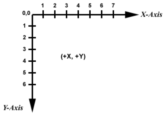
The Flight Simulator Coordinate System
Selecting the value of the numbers themselves can be a little mysterious because they are based on a position against a background image. But since so many tools can help you position gauges, and you can always use trial-and-error to position them, there is no need (or time) for us to go into the detail of exactly what those numbers represent. For more information about that, read the Panels SDK in the simulator documentation.
- Width, Height - size of the gauge
- 5th parameter - optional, defined by the gauge programmer
Most gauge lines will include the X, Y, Width and Height parameters, which is four parameters. Sometimes, you can omit the Height, and flight simulator will figure out what height to use based on the Width you requested. In other cases you can leave out both the Width and the Height parameters, and flight simulator will use the default size of the gauge.
But the 5th parameter is special. The more advanced Mindstar Aviation gauges like GPS's make use of the 5th parameter, and it is very important that it truly be the 5th parameter on the line. This means that if you have chosen to omit the Width or the Height, you still need to put the comma on the line so that the 5th parameter appears after the correct number of commas. The 5th parameter is defined by the programmer of a particular gauge. There is no standard way to use it, and it's completely up to the programmer to explain how it should be used with his or her particular gauge software. We will explain how the 5th parameter is relevant to Mindstar Aviation gauges in a later section.
Important: The Optional 5th Parameter
Most gauge lines will include the X, Y, Width and Height parameters, which is four parameters. Sometimes, you can omit the Height, and flight simulator will figure out what height to use based on the Width you requested. In other cases you can leave out both the Width and the Height parameters, and flight simulator will use the default size of the gauge.
But the 5th parameter is special. The more advanced Mindstar Aviation gauges like GPS's make use of the 5th parameter, and it is very important that it truly be the 5th parameter on the line. This means that if you have chosen to omit the Width or the Height, you still need to put the comma on the line so that the 5th parameter appears after the correct number of commas. The 5th parameter is defined by the programmer of a particular gauge. There is no standard way to use it, and it's completely up to the programmer to explain how it should be used with his or her particular gauge software. We will explain how the 5th parameter is relevant to Mindstar Aviation gauges in a later section.
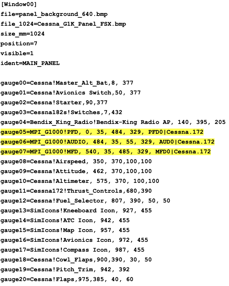
Example - Cessna 172 2D Cockpit with G1000
Below is an example of a [Window00] section from a Cessna 172 panel.cfg configured with G1000 avionics. Notice the highlighted G1000 gauge lines (gauge05, gauge06, gauge07) which use MPI_G1000 as the GaugeFile and include "Cessna.172" as the 5th parameter:
Popup Windows
In the previous sections, we described how the [Window00] section in the panel.cfg defines the layout of gauges in the 2D cockpit. All additional [Window**] sections are popup windows. The title of the popup window is defined in the [Window Titles] section. That section is just a listing of the titles to be used, one per line, starting with Window01 through WindowNN, where NN is simply the last popup window in your panel. Popup windows work the same way as Window00, with gauge lines that specify which gauges appear in the popup and their positions.
The 3D Virtual Cockpit
If you have used flight simulator for a while, you have probably noticed that there are two different "modes" you can display for the cockpit. The 2D cockpit shows all the instruments flat on the screen without any perspective. This is the mode that is most appropriate when displaying gauges inside hardware enclosures or in professional flight simulators. But for home and entertainment use, and for certain professional applications, there is a more immersive mode that lets you look left and right inside the cockpit and see everything as if you were sitting in the pilot's seat. If you look down, you see the seat; if you look forward, you see the control panel, and if you look back behind you, you can see the passenger seats. This is the 3D cockpit, also known as the Virtual Cockpit or VC.
The VC is a combination of two different parts of the aircraft container. The 3D shapes of the cockpit itself are part of the aircraft model. It is not something you can edit, it is an integral part of the model stored in the model folder, and only the modeller/artist who created it can change it. But if the VC is part of the 3D model, and the 3D model has no color until the simulator wraps (skins) it with the images from the texture folder (remember the skinning of the exterior of the airplane), then how is it that we can see these beautiful immersive cockpits in the VC?
It happens because instead of wrapping the VC with simple static images from a texture file, the simulator wraps parts of the VC with the images generated by the gauges themselves. The bumps and shapes of the 3D model become colored by the gauge image generated by the gauge software. With proper positioning of the gauges over the 3-dimensional shapes of the model, it makes the gauges appear to be three-dimensional.
At this point, it's important to emphasize that there is nothing 3-dimensional about gauges. Gauges are always only 2-dimensional flat images. There is nothing a gauge programmer can do to make a gauge either work, or not work, in the VC. The ability to incorporate a gauge into the 3D model of the VC is completely dependent on how the person or company created the 3D model.
Will Your Gauge Work In The VC?
We often get questions asking whether our software will work in the VC. Unfortunately, this is not a question we can answer. This question needs to be directed to the company or person who created the aircraft model you are using. We don't (and can't) do anything to prevent our software from being used in the VC. Your level of success with editing VCs will be dependent on decisions made by the modeller, so please direct VC-related questions to the vendor of your aircraft.
Modifying Gauges In The VC
With all that said, you still have a shot at modifying gauges in the VC. The layout of the gauges in the VC are controlled by the gauge lines in the [VCockpit**] section of the panel.cfg. It is best to limit your changes to the VC gauges by replacing one instrument with another of a similar size and shape. The easiest starting point is to find a gauge made by one manufacturer that you want to replace with the same type of gauge from another manufacturer.
When you modify the gauge line associated with the gauge you are trying to replace, try to change only the GaugeFile and GaugeName portion of the line. Leave the X, Y, Width and Height parameters as-is. This gives you a best first-shot at positioning the new gauge exactly where the old one used to be. Just remember, if the new gauge requires a different format of 5th parameter, be sure to enter the 5th parameter in the way expected by the new gauge you are trying to use.
Multiple Panel Folders and Aircraft Variations
It's important to understand that an aircraft container can have more than one panel folder. Each panel folder represents a different cockpit variation. The default panel folder is simply called panel, but you can create additional panel folders with descriptive names.
But just because you create a panel folder doesn't mean that flight simulator knows to use it. You have to tell flight simulator about these new panel folders in the aircraft.cfg file. Aircraft variations (defined by the [fltsim.#] sections in the aircraft.cfg) can refer to different panel folders. This is how you can have multiple cockpit configurations for the same aircraft model.
Naming Panel Folders
Additional panel folders must start with the word "panel" followed by a period and then a descriptive name:
By default, if a [fltsim.#] section does not specify a panel folder, flight simulator will use the default panel folder. Here's an example showing aircraft variations that use the default panel folder:
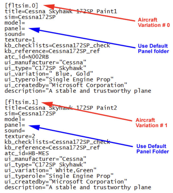
Example of Aircraft Variations That Use The Default Panel Folder
Now imagine if we created a new panel folder named panel.mpi_gns. In order for that new panel folder to be recognized by flight simulator, we need to add a [fltsim.#] section to the aircraft config that tells flight simulator about our new cockpit variation. (see image below).
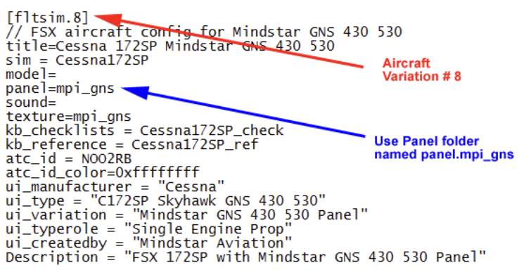
Example of an Aircraft Variation That Uses a Named Panel Folder
Aircraft Variation Titles
The Title= line in the aircraft.cfg must always be unique. No other aircraft variation can use this name - not just inside this particular aircraft.cfg, but across all variations in all airplanes in the entire simulator.
For this reason, it's best to make the title something that includes both the airplane and some identifying aspect of the control panel. It's also good practice to make corresponding changes to the ui_variation and description items too. This ensures that no matter how you view the airplane in flight simulator, you will see something that clearly identifies what this variation is intended to display.
Tip: Always back up your aircraft container folders before making manual modifications. This ensures you can restore working configurations if something goes wrong.